 電子發燒友App


摘要:DS2482是I2C到1-Wire的橋接器件。DS2482可以使任何具備I2C通信功能的主機產生正確時序和具有擺率控制的1-Wire波形。本應用筆記是DS2482 I2C至1-Wire線驅動器的用戶指南,詳細介紹了通用1-Wire主控制器操作的通信過程。
本文僅作為DS2482數據資料的補充,并不能替代數據資料。DS2482可提供兩種配置,單通道1-Wire主控制器(DS2482-100)和帶有低功耗休眠模式的1-Wire主控制器(DS2482-101),以及八通道1-Wire主控制器(DS2482-800)。

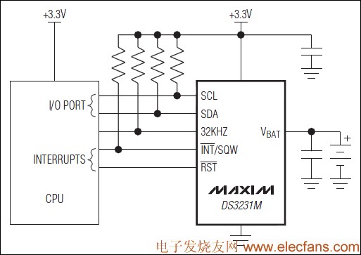
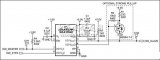
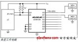
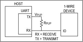
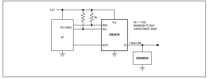
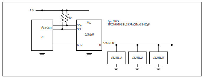
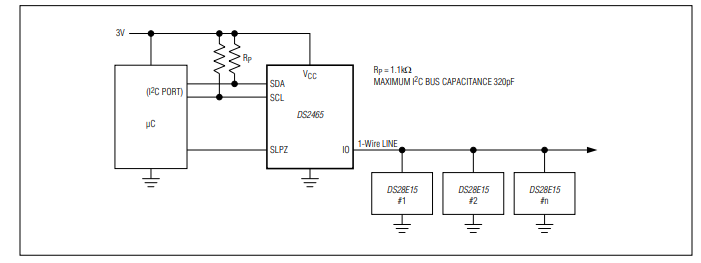
圖1. 實現I2C與1-Wire網絡通信的DS2482橋接器功能簡圖
1-Wire搜索算法也可以利用相同的三個原始函數構成。通1-Wire的三個命令,DS2482可以執行搜索功能,大大降低了搜索操作所需的通信量。同樣,單字節的1-Wire通信命令要比八次逐位操作效率更高。
表1所示是三個基本原函數(OWReset、OWWriteBit/OWReadBit和OWWriteByte/OWReadByte)以及其它三個非常有用的函數(OWBlock、OWSearch和msDelay),它們構成了一系列主要的基本1-Wire操作。這些操作名稱將在下文中使用。
表1. 基本的1-Wire操作
許多1-Wire從器件可以工作在兩種不同的通信速率下:標準速率和高速模式。所有器件都支持標準速率模式。高速速率大約是標準速率的10倍。DS2482同時支持這兩種1-Wire速率。
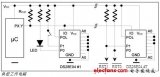
1-Wire器件通常從1-Wire總線上獲取部分或全部工作電源。不過有些器件在協議的特定操作中需要額外供電。例如,某個器件可能需要進行溫度轉換或執行SHA-1散列算法。這種操作的電源是通過使能1-Wire總線的強上拉提供的。這種供電方式下,不能進行正常通信。DS2482通過設置強上拉標志(SPU)位供電,這將在1-Wire的下一個字節/位通信完成后啟動強上拉。DS2482-100和DS2482-101還具有一個外部引腳(PCTLZ),可控制大電流強上拉。
表2列出了用于1-Wire速率設定、供電和編程脈沖的擴展1-Wire操作。
表2. 擴展的1-Wire操作
表3. 所需要的I2C主機操作

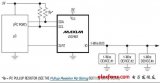
圖2. DS2482的I2C從地址
I2C通信過程—符號說明
本文中許多圖中的數據方向表示方法指出了通信方向是主機到從機(灰色),還是從機到主機(白色)。

圖3. 上電后進行器件復位。該實例包括可選的讀訪問,以檢驗命令是否成功執行。

圖4. 寫配置寄存器,該實例中包括可選擇的讀操作,用于驗證是否成功執行命令。

圖5. 寫通道選擇寄存器,該實例中包括可選擇的讀操作,用于驗證是否成功執行命令。

圖6. 1-Wire復位。開始或終止1-Wire通信。連續檢測1-Wire的空閑(1WB = 0)、忙狀態,直到1-Wire命令完成為止,等到1-Wire命令執行完成,然后讀取結果。

圖7. 1-Wire位,在1-Wire總線上生成一個時隙,當1WB從1變為0時,狀態寄存器保持1-Wire位命令的有效結果。

圖8. 1-Wire的一個數據字節

圖9. 1-Wire寫字節。向1-Wire總線發送命令代碼。當1WB從1變為0時,完成1-Wire寫字節命令。

圖10. 1-Wire讀字節。從1-Wire總線上讀取一個字節。連續檢測狀態寄存器直到1WB位從1變為0。然后設置讀指針指向讀數據寄存器(代碼E1h),并再次訪問該器件,讀取從1-Wire總線上得到的數據字節。
三合一命令(78h)可在1-Wire總線上產生3個時隙,其中包括兩個讀時隙和一個寫時隙。狀態寄存器中的方向字節(DIR)決定了寫時隙的類型(圖11)。例10介紹了完整的1-Wire搜索過程,采用1-Wire三合一命令。調用OWFirst,然后重復調用OWNext,可以查找到1-Wire網絡的所有器件。有關1-Wire搜索算法的詳細介紹請參考應用筆記187,“1-Wire搜索算法”。
圖11. 1-Wire三合一命令,在1-Wire總線上實現搜索ROM功能。完成該1-Wire功能需要空閑時間。然后在讀模式下訪問器件,通過1-Wire三合一命令得到結果。
引言
1-Wire網絡包括一個主機和一個或多個從機器件,1-Wire主機可以由微處理器的一個I/O引腳構成,手動產生定時脈沖。DS2482 I2C至1-Wire網絡的橋接器件可以產生詳細的1-Wire通信時序,無需工程師參與設計。圖1所示為DS2482配置的簡化框圖。本文介紹了采用DS2482實現應用程序接口(API)有效方法,支持基本的和擴展的1-Wire操作。詳細介紹了對應于1-Wire操作的I2C通信。這些操作為執行當前和未來1-Wire器件的所有功能打下了全面的基礎,但基于DS250x系列EPROM的器件編程除外。以這種方式概要介紹1-Wire操作,適合不依賴1-Wire主機的1-Wire應用。本文僅作為DS2482數據資料的補充,并不能替代數據資料。DS2482可提供兩種配置,單通道1-Wire主控制器(DS2482-100)和帶有低功耗休眠模式的1-Wire主控制器(DS2482-101),以及八通道1-Wire主控制器(DS2482-800)。
圖1. 實現I2C與1-Wire網絡通信的DS2482橋接器功能簡圖
1-Wire接口
下面給出幾個基本的1-Wire函數,稱之為原函數,也就是為了執行所有1-Wire操作,應用中必須具備的函數。第一個函數(OWReset)是使網絡上所有1-Wire從器件復位,為接收來自1-Wire主控制器的指令做好準備。第二個函數(OWWriteBit)完成1-Wire主控制器向從器件寫入一位的操作,而第三個函數(OWReadBit)完成從1-Wire從器件中讀取一位的操作。由于必須由1-Wire主控制器啟動所有的1-Wire位通信,所以“讀取”實際上是在“寫入”一位后采樣得到的結果。幾乎所有其他1-Wire操作都可以由這三個操作構成。例如,向1-Wire網絡寫1個字節相當于8次寫一位操作。1-Wire搜索算法也可以利用相同的三個原始函數構成。通1-Wire的三個命令,DS2482可以執行搜索功能,大大降低了搜索操作所需的通信量。同樣,單字節的1-Wire通信命令要比八次逐位操作效率更高。
表1所示是三個基本原函數(OWReset、OWWriteBit/OWReadBit和OWWriteByte/OWReadByte)以及其它三個非常有用的函數(OWBlock、OWSearch和msDelay),它們構成了一系列主要的基本1-Wire操作。這些操作名稱將在下文中使用。
表1. 基本的1-Wire操作
| Operation | Description |
| OWReset | Sends the 1-Wire reset stimulus and check for the presence pulse of 1-Wire slave devices. |
| OWWriteBit/OWReadBit | Sends to or receives from the 1-Wire network a single bit of data. |
| OWWriteByte/OWReadByte | Sends to or receives from the 1-Wire network a single byte of data. |
| OWBlock | Sends to and receives from the 1-Wire network multiple bytes of data. |
| OWSearch | Performs the 1-Wire Search Algorithm (see application note 187). |
| msDelay | Delays at least the specified number of milliseconds. Used for timing strong pullup operations. |
許多1-Wire從器件可以工作在兩種不同的通信速率下:標準速率和高速模式。所有器件都支持標準速率模式。高速速率大約是標準速率的10倍。DS2482同時支持這兩種1-Wire速率。
1-Wire器件通常從1-Wire總線上獲取部分或全部工作電源。不過有些器件在協議的特定操作中需要額外供電。例如,某個器件可能需要進行溫度轉換或執行SHA-1散列算法。這種操作的電源是通過使能1-Wire總線的強上拉提供的。這種供電方式下,不能進行正常通信。DS2482通過設置強上拉標志(SPU)位供電,這將在1-Wire的下一個字節/位通信完成后啟動強上拉。DS2482-100和DS2482-101還具有一個外部引腳(PCTLZ),可控制大電流強上拉。
表2列出了用于1-Wire速率設定、供電和編程脈沖的擴展1-Wire操作。
表2. 擴展的1-Wire操作
| Operation | Description |
| OWSpeed | Sets the 1-Wire communication speed, either standard or overdrive. Note that this only changes the communication speed of the 1-Wire master; the 1-Wire slave device must be instructed to make the switch when going from normal to overdrive. The 1-Wire slave will always revert to standard speed when it encounters a standard-speed 1-Wire reset. |
| OWLevel | Sets the 1-Wire power level (normal or power delivery). |
| OWReadBitPower | Reads a single bit of data from the 1-Wire network and optionally applies power delivery immediately after the bit is complete. |
| OWWriteBytePower | Sends a single byte of data to the 1-Wire network and applies power delivery immediately after the byte is complete. |
主機配置
DS2482的主機應具有一個I2C通信口,本文并沒有講述主機的配置。然而,主機必須提供標準I2C接口操作。需要注意的是,主機接口具有包含一些I2C接口操作的高級函數。所需操作請參考表3。表3. 所需要的I2C主機操作
| Operation | Description |
| I2C_start | I2C start command. |
| I2C_rep_start | I2C repeated start command. |
| I2C_stop | I2C stop command. |
| I2C_write | Writes a byte to the I2C bus. The byte to write is passed to the function. |
| I2C_read | Reads a byte from the I2C bus. The byte read is returned from the function. |
配置DS2482
在嘗試1-Wire操作之前,主機必須設置I2C至1-Wire線驅動器DS2482,并與其同步。要與DS2482通信,主機必須知道其從地址。圖2所示為DS2482-100、DS2482-101和DS2482-800的從地址。圖2. DS2482的I2C從地址
DS2482的I2C命令
下列符號說明來自于DS2482數據資料,以簡寫符號表示,用來說明器件的I2C通信過程。接下來,我們會重復這些通信過程,并為實現基本的和擴展的1-Wire操作提供附加注釋和C語言例程。I2C通信過程—符號說明
| Symbol | Description |
| S | START Condition |
| AD, 0 | Select DS2482 for Write Access |
| AD, 1 | Select DS2482 for Read Access |
| Sr | Repeated START Condition |
| P | STOP Condition |
| A | Acknowledged |
| A\ | Not acknowledged |
| (Idle) | Bus not busy |
| Transfer of one byte | |
| DRST | Command 'Device Reset', F0h |
| WCFG | Command 'Write Configuration', D2h |
| CHSL | Command 'Channel Select', C3h (DS2482-800 only) |
| SRP | Command 'Set Read Pointer', E1h |
| 1WRS | Command '1-Wire Reset', B4h |
| 1WWB | Command '1-Wire Write Byte', A5h |
| 1WRB | Command '1-Wire Read Byte', 96h |
| 1WSB | Command '1-Wire Single Bit', 87h |
| 1WT | Command '1-Wire Triplet', 78h |
數據方向表示法
| Master-to-Slave | Slave-to-Master |
本文中許多圖中的數據方向表示方法指出了通信方向是主機到從機(灰色),還是從機到主機(白色)。
DS2482配置操作
以下操作用于設置、配置DS2482,有些操作需要調用1-Wire操作的子程序。DS2482檢測
例1所示C程序提供檢測和配置流程,寫入DS2482的默認值包括1-Wire速率(標準)、強上拉(關斷)、在線脈沖屏蔽(關斷)和有源上拉(通)。該狀態保持為通用變量,如果器件需要復位到該默認狀態可以進行恢復。針對不同應用可以選擇不同的默認值。// DS2482 state
unsigned char I2C_address;
int c1WS, cSPU, cPPM, cAPU;
int short_detected;
//--------------------------------------------------------------------------
// DS2428 Detect routine that sets the I2C address and then performs a
// device reset followed by writing the configuration byte to default values:
// 1-Wire speed (c1WS) = standard (0)
// Strong pullup (cSPU) = off (0)
// Presence pulse masking (cPPM) = off (0)
// Active pullup (cAPU) = on (CONFIG_APU = 0x01)
//
// Returns: TRUE if device was detected and written
// FALSE device not detected or failure to write configuration byte
//
int DS2482_detect(unsigned char addr)
{
// set global address
I2C_address = addr;
// reset the DS2482 ON selected address
if (!DS2482_reset())
return FALSE;
// default configuration
c1WS = FALSE;
cSPU = FALSE;
cPPM = FALSE;
cAPU = CONFIG_APU;
// write the default configuration setup
if (!DS2482_write_config(c1WS | cSPU | cPPM | cAPU))
return FALSE;
return TRUE;
}
例1. DS2482檢測DS2482器件復位
圖3是DS2482器件復位I2C通信的流程。例2給出了DS2482復位命令的C程序,可實現器件狀態機邏輯的完全復位,并終止所有正在進行的1-Wire通信。器件的復位命令代碼是F0h。圖3. 上電后進行器件復位。該實例包括可選的讀訪問,以檢驗命令是否成功執行。
//--------------------------------------------------------------------------
// Perform a device reset on the DS2482
//
// Returns: TRUE if device was reset
//          FALSE device not detected or failure to perform reset
//
int DS2482_reset()
{
   unsigned char status;

   // Device Reset
   //   S AD,0 [A] DRST [A] Sr AD,1 [A] [SS] A\ P
   //  [] indicates from slave
   //  SS status byte to read to verify state

   I2C_start();
   I2C_write(I2C_address | I2C_WRITE, EXPECT_ACK);
   I2C_write(CMD_DRST, EXPECT_ACK);
   I2C_rep_start();
   I2C_write(I2C_address | I2C_READ, EXPECT_ACK);
   status = I2C_read(NACK);
   I2C_stop();

   // check for failure due to incorrect read back of status
   return ((status & 0xF7) == 0x10);
}
例2. 復位器件代碼DS2482寫配置
圖4所示為DS2482寫配置的I2C通信例程;例3所示為實現DS2482寫配置命令時序的C程序。寫配置命令代碼為D2h。圖4. 寫配置寄存器,該實例中包括可選擇的讀操作,用于驗證是否成功執行命令。
//--------------------------------------------------------------------------
// Write the configuration register in the DS2482. The configuration
// options are provided in the lower nibble of the provided config byte.
// The uppper nibble in bitwise inverted when written to the DS2482.
//
// Returns:  TRUE: config written and response correct
//           FALSE: response incorrect
//
int DS2482_write_config(unsigned char config)
{
   unsigned char read_config;

   // Write configuration (Case A)
   //   S AD,0 [A] WCFG [A] CF [A] Sr AD,1 [A] [CF] A\ P
   //  [] indicates from slave
   //  CF configuration byte to write

   I2C_start();
   I2C_write(I2C_address | I2C_WRITE, EXPECT_ACK);
   I2C_write(CMD_WCFG, EXPECT_ACK);
   I2C_write(config | (~config << 4), EXPECT_ACK);
   I2C_rep_start();
   I2C_write(I2C_address | I2C_READ, EXPECT_ACK);
   read_config = I2C_read(NACK);
   I2C_stop();

   // check for failure due to incorrect read back
   if (config != read_config)
   {
      // handle error
      // ...
      DS2482_reset();

      return FALSE;
   }

   return TRUE;
}
例3. DS2482寫配置 DS2482通道選擇
圖5所示為實現DS2482-800通道選擇的I2C通信實例,有效通道為0至7。注意,該操作不適合DS2482-100或DS2482-101。例4給出了執行DS2482-800通道選擇命令的C程序,通道選擇命令碼為C3h。選擇通道后,選中通道可執行所有1-Wire操作。圖5. 寫通道選擇寄存器,該實例中包括可選擇的讀操作,用于驗證是否成功執行命令。
//--------------------------------------------------------------------------
// Select the 1-Wire channel on a DS2482-800.
//
// Returns: TRUE if channel selected
//          FALSE device not detected or failure to perform select
//
int DS2482_channel_select(int channel)
{
   unsigned char ch, ch_read, check;

   // Channel Select (Case A)
   //   S AD,0 [A] CHSL [A] CC [A] Sr AD,1 [A] [RR] A\ P
   //  [] indicates from slave
   //  CC channel value
   //  RR channel read back

   I2C_start();
   I2C_write(I2C_address | I2C_WRITE, EXPECT_ACK);
   I2C_write(CMD_CHSL, EXPECT_ACK);

   switch (channel)
   {
      default: case 0: ch = 0xF0; ch_read = 0xB8; break;
      case 1: ch = 0xE1; ch_read = 0xB1; break;
      case 2: ch = 0xD2; ch_read = 0xAA; break;
      case 3: ch = 0xC3; ch_read = 0xA3; break;
      case 4: ch = 0xB4; ch_read = 0x9C; break;
      case 5: ch = 0xA5; ch_read = 0x95; break;
      case 6: ch = 0x96; ch_read = 0x8E; break;
      case 7: ch = 0x87; ch_read = 0x87; break;
   };

   I2C_write(ch, EXPECT_ACK);
   I2C_rep_start();
   I2C_write(I2C_address | I2C_READ, EXPECT_ACK);
   check = I2C_read(NACK);
   I2C_stop();

   // check for failure due to incorrect read back of channel
   return (check == ch_read);
}
例4. DS2482-800通道選擇DS2482的1-Wire操作
OWReset
1-Wire Reset命令(B4h)在1-Wire總線上執行1-Wire復位和1-Wire器件在線應答脈沖檢測。通過狀態寄存器中的在線應答脈沖檢測(PPD)和短路檢測(SD)字段,可以采樣和報告1-Wire總線的狀態。圖6所示為1-Wire復位命令的I2C通信流程。例5為發送命令的C程序,將檢查狀態寄存器以確定在線應答脈沖狀態。圖6. 1-Wire復位。開始或終止1-Wire通信。連續檢測1-Wire的空閑(1WB = 0)、忙狀態,直到1-Wire命令完成為止,等到1-Wire命令執行完成,然后讀取結果。
//--------------------------------------------------------------------------
// Reset all of the devices on the 1-Wire Net and return the result.
//
// Returns: TRUE(1):  presence pulse(s) detected, device(s) reset
//          FALSE(0): no presence pulses detected
//
int OWReset(void)
{
   unsigned char status;
   int poll_count = 0;

   // 1-Wire reset (Case B)
   //   S AD,0 [A] 1WRS [A] Sr AD,1 [A] [Status] A [Status] A\ P
   //                                   \--------/
   //                       Repeat until 1WB bit has changed to 0
   //  [] indicates from slave

   I2C_start();
   I2C_write(I2C_address | I2C_WRITE, EXPECT_ACK);
   I2C_write(CMD_1WRS, EXPECT_ACK);
   I2C_rep_start();
   I2C_write(I2C_address | I2C_READ, EXPECT_ACK);

   // loop checking 1WB bit for completion of 1-Wire operation
   // abort if poll limit reached
   status = I2C_read(ACK);
   do
   {
      status = I2C_read(status & STATUS_1WB);
   }
   while ((status & STATUS_1WB) && (poll_count++ < POLL_LIMIT));

   I2C_stop();

   // check for failure due to poll limit reached
   if (poll_count >= POLL_LIMIT)
   {
      // handle error
      // ...
      DS2482_reset();
      return FALSE;
   }

   // check for short condition
   if (status & STATUS_SD)
      short_detected = TRUE;
   else
      short_detected = FALSE;

   // check for presence detect
   if (status & STATUS_PPD)
      return TRUE;
   else
      return FALSE;
}
例5. OWReset代碼OWWriteBit/OWReadBit
1-Wire位命令(0x87)生成一個1-Wire位時隙。圖7所示是1-Wire位命令的I2C通信C程序。圖8時字節的位分配,V是發送位。例6給出了OWWriteBit、OWReadBit和OWTouchBit程序。圖7. 1-Wire位,在1-Wire總線上生成一個時隙,當1WB從1變為0時,狀態寄存器保持1-Wire位命令的有效結果。
圖8. 1-Wire的一個數據字節
//--------------------------------------------------------------------------
// Send 1 bit of communication to the 1-Wire Net.
// The parameter 'sendbit' least significant bit is used.
//
// 'sendbit' - 1 bit to send (least significant byte)
//
void OWWriteBit(unsigned char sendbit)
{
   OWTouchBit(sendbit);
}

//--------------------------------------------------------------------------
// Reads 1 bit of communication from the 1-Wire Net and returns the
// result
//
// Returns:  1 bit read from 1-Wire Net
//
unsigned char OWReadBit(void)
{
   return OWTouchBit(0x01);
}

//--------------------------------------------------------------------------
// Send 1 bit of communication to the 1-Wire Net and return the
// result 1 bit read from the 1-Wire Net. The parameter 'sendbit'
// least significant bit is used and the least significant bit
// of the result is the return bit.
//
// 'sendbit' - the least significant bit is the bit to send
//
// Returns: 0:   0 bit read from sendbit
//          1:   1 bit read from sendbit
//
unsigned char OWTouchBit(unsigned char sendbit)
{
   unsigned char status;
   int poll_count = 0;

   // 1-Wire bit (Case B)
   //   S AD,0 [A] 1WSB [A] BB [A] Sr AD,1 [A] [Status] A [Status] A\ P
   //                                          \--------/
   //                           Repeat until 1WB bit has changed to 0
   //  [] indicates from slave
   //  BB indicates byte containing bit value in msbit

   I2C_start();
   I2C_write(I2C_address | I2C_WRITE, EXPECT_ACK);
   I2C_write(CMD_1WSB, EXPECT_ACK);
   I2C_write(sendbit ? 0x80 : 0x00, EXPECT_ACK);
   I2C_rep_start();
   I2C_write(I2C_address | I2C_READ, EXPECT_ACK);

   // loop checking 1WB bit for completion of 1-Wire operation
   // abort if poll limit reached
   status = I2C_read(ACK);
   do
   {
      status = I2C_read(status & STATUS_1WB);
   }
   while ((status & STATUS_1WB) && (poll_count++ < POLL_LIMIT));

   I2C_stop();

   // check for failure due to poll limit reached
   if (poll_count >= POLL_LIMIT)
   {
      // handle error
      // ...
      DS2482_reset();
      return 0;
   }

   // return bit state
   if (status & STATUS_SBR)
      return 1;
   else
      return 0;
}
例6. 1-Wire位命令
OWWriteByte
1-Wire寫字節命令(A5h)向1-Wire總線寫入單個數據字節。在DS2482執行該命令之前,必須結束1-Wire的工作狀態。圖9所示為通過I2C寫1-Wire字節的情況。例7中的程序在從該操作返回前檢查1-Wire是否完成有效的操作。圖9. 1-Wire寫字節。向1-Wire總線發送命令代碼。當1WB從1變為0時,完成1-Wire寫字節命令。
//--------------------------------------------------------------------------
// Send 8 bits of communication to the 1-Wire Net and verify that the
// 8 bits read from the 1-Wire Net are the same (write operation).
// The parameter 'sendbyte' least significant 8 bits are used.
//
// 'sendbyte' - 8 bits to send (least significant byte)
//
// Returns:  TRUE: bytes written and echo was the same
//           FALSE: echo was not the same
//
void OWWriteByte(unsigned char sendbyte)
{
   unsigned char status;
   int poll_count = 0;

   // 1-Wire Write Byte (Case B)
   //   S AD,0 [A] 1WWB [A] DD [A] Sr AD,1 [A] [Status] A [Status] A\ P
   //                                          \--------/
   //                             Repeat until 1WB bit has changed to 0
   //  [] indicates from slave
   //  DD data to write

   I2C_start();
   I2C_write(I2C_address | I2C_WRITE, EXPECT_ACK);
   I2C_write(CMD_1WWB, EXPECT_ACK);
   I2C_write(sendbyte, EXPECT_ACK);
   I2C_rep_start();
   I2C_write(I2C_address | I2C_READ, EXPECT_ACK);

   // loop checking 1WB bit for completion of 1-Wire operation
   // abort if poll limit reached
   status = I2C_read(ACK);
   do
   {
      status = I2C_read(status & STATUS_1WB);
   }
   while ((status & STATUS_1WB) && (poll_count++ < POLL_LIMIT));

   I2C_stop();

   // check for failure due to poll limit reached
   if (poll_count >= POLL_LIMIT)
   {
      // handle error
      // ...
      DS2482_reset();
   }
}
例7. OWWriteByte程序OWReadByte
1-Wire讀字節命令(96h)從1-Wire網絡讀取單個數據字節。在DS2482執行該命令之前,必須等1-Wire的工作狀態結束。圖10所示為I2C通信流程,1-Wire讀字節命令程序如例8。發送讀字節命令之前,必須檢查1-Wire的工作狀態是否結束。圖10. 1-Wire讀字節。從1-Wire總線上讀取一個字節。連續檢測狀態寄存器直到1WB位從1變為0。然后設置讀指針指向讀數據寄存器(代碼E1h),并再次訪問該器件,讀取從1-Wire總線上得到的數據字節。
//--------------------------------------------------------------------------
// Send 8 bits of read communication to the 1-Wire Net and return the
// result 8 bits read from the 1-Wire Net.
//
// Returns:  8 bits read from 1-Wire Net
//
unsigned char OWReadByte(void)
{
   unsigned char data, status;
   int poll_count = 0;

   // 1-Wire Read Bytes (Case C)
   //   S AD,0 [A] 1WRB [A] Sr AD,1 [A] [Status] A [Status] A\
   //                                   \--------/
   //                     Repeat until 1WB bit has changed to 0
   //   Sr AD,0 [A] SRP [A] E1 [A] Sr AD,1 [A] DD A\ P
   //
   //  [] indicates from slave
   //  DD data read

   I2C_start();
   I2C_write(I2C_address | I2C_WRITE, EXPECT_ACK);
   I2C_write(CMD_1WRB, EXPECT_ACK);
   I2C_rep_start();
   I2C_write(I2C_address | I2C_READ, EXPECT_ACK);

   // loop checking 1WB bit for completion of 1-Wire operation
   // abort if poll limit reached
   status = I2C_read(ACK);
   do
   {
      status = I2C_read(status & STATUS_1WB);
   }
   while ((status & STATUS_1WB) && (poll_count++ < POLL_LIMIT));

   // check for failure due to poll limit reached
   if (poll_count >= POLL_LIMIT)
   {
      // handle error
      // ...
      DS2482_reset();
      return 0;
   }

   I2C_rep_start();
   I2C_write(I2C_address | I2C_WRITE, EXPECT_ACK);
   I2C_write(CMD_SRP, EXPECT_ACK);
   I2C_write(0xE1, EXPECT_ACK);
   I2C_rep_start();
   I2C_write(I2C_address | I2C_READ, EXPECT_ACK);
   data =  I2C_read(NACK);
   I2C_stop();

   return data;
}
例8. OWReadByte程序OWBlock
OWBlock用于執行一組1-Wire字節操作,對于1-Wire網絡的數據塊傳輸非常有用。例9所示為OWBlock例程。//--------------------------------------------------------------------------
// The 'OWBlock' transfers a block of data to and from the
// 1-Wire Net. The result is returned in the same buffer.
//
// 'tran_buf' - pointer to a block of unsigned
// chars of length 'tran_len' that will be sent
// to the 1-Wire Net
// 'tran_len' - length in bytes to transfer
//
void OWBlock(unsigned char *tran_buf, int tran_len)
{
int i;
for (i = 0; i < tran_len; i++)
tran_buf[i] = OWTouchByte(tran_buf[i]);
}
//--------------------------------------------------------------------------
// Send 8 bits of communication to the 1-Wire Net and return the
// result 8 bits read from the 1-Wire Net. The parameter 'sendbyte'
// least significant 8 bits are used and the least significant 8 bits
// of the result are the return byte.
//
// 'sendbyte' - 8 bits to send (least significant byte)
//
// Returns: 8 bits read from sendbyte
//
unsigned char OWTouchByte(unsigned char sendbyte)
{
if (sendbyte == 0xFF)
return OWReadByte();
else
{
OWWriteByte(sendbyte);
return sendbyte;
}
}
例9. OWBlock程序OWSearch/1-Wire的三合一命令
1-Wire搜索命令用于搜索1-Wire網絡中每個器件唯一的64位注冊碼,這個唯一的注冊碼通常在數據資料中用ROM碼表示,因為它存儲在只讀存儲器。搜索從1-Wire復位開始,隨后是搜索命令。所有1-Wire器件應答的搜索命令是F0h。搜索命令之后,1-Wire主機將進行二叉樹搜索,找到一個器件。二叉樹搜索通過以下操作判斷64位的每一位:首先讀一位,讀取該位的補碼,然后寫入一位以確定留在搜索中的器件。這三個單獨的位操作時序稱為三合一操作。DS2482帶有一個簡短命令,利用該三合一命令可以更高效地執行1-Wire搜索。三合一命令(78h)可在1-Wire總線上產生3個時隙,其中包括兩個讀時隙和一個寫時隙。狀態寄存器中的方向字節(DIR)決定了寫時隙的類型(圖11)。例10介紹了完整的1-Wire搜索過程,采用1-Wire三合一命令。調用OWFirst,然后重復調用OWNext,可以查找到1-Wire網絡的所有器件。有關1-Wire搜索算法的詳細介紹請參考應用筆記187,“1-Wire搜索算法”。
圖11. 1-Wire三合一命令,在1-Wire總線上實現搜索ROM功能。完成該1-Wire功能需要空閑時間。然后在讀模式下訪問器件,通過1-Wire三合一命令得到結果。
// Search state
unsigned char ROM_NO[8];
int LastDiscrepancy;
int LastFamilyDiscrepancy;
int LastDeviceFlag;
unsigned char crc8;

//--------------------------------------------------------------------------
// Find the 'first' devices on the 1-Wire network
// Return TRUE  : device found, ROM number in ROM_NO buffer
//        FALSE : no device present
//
int OWFirst()
{
   // reset the search state
   LastDiscrepancy = 0;
   LastDeviceFlag = FALSE;
   LastFamilyDiscrepancy = 0;

   return OWSearch();
}

//--------------------------------------------------------------------------
// Find the 'next' devices on the 1-Wire network
// Return TRUE  : device found, ROM number in ROM_NO buffer
//        FALSE : device not found, end of search
//
int OWNext()
{
   // leave the search state alone
   return OWSearch();
}

//--------------------------------------------------------------------------
// The 'OWSearch' function does a general search. This function
// continues from the previous search state. The search state
// can be reset by using the 'OWFirst' function.
// This function contains one parameter 'alarm_only'.
// When 'alarm_only' is TRUE (1) the find alarm command
// 0xEC is sent instead of the normal search command 0xF0.
// Using the find alarm command 0xEC will limit the search to only
// 1-Wire devices that are in an 'alarm' state.
//
// Returns:   TRUE (1) : when a 1-Wire device was found and its
//                       Serial Number placed in the global ROM
//            FALSE (0): when no new device was found.  Either the
//                       last search was the last device or there
//                       are no devices on the 1-Wire Net.
//
int OWSearch()
{
   int id_bit_number;
   int last_zero, rom_byte_number, search_result;
   int id_bit, cmp_id_bit;
   unsigned char rom_byte_mask, search_direction, status;

   // initialize for search
   id_bit_number = 1;
   last_zero = 0;
   rom_byte_number = 0;
   rom_byte_mask = 1;
   search_result = FALSE;
   crc8 = 0;

   // if the last call was not the last one
   if (!LastDeviceFlag)
   {
      // 1-Wire reset
      if (!OWReset())
      {
         // reset the search
         LastDiscrepancy = 0;
         LastDeviceFlag = FALSE;
         LastFamilyDiscrepancy = 0;
         return FALSE;
      }

      // issue the search command
      OWWriteByte(0xF0);

      // loop to do the search
      do
      {
         // if this discrepancy if before the Last Discrepancy
         // on a previous next then pick the same as last time
         if (id_bit_number < LastDiscrepancy)
         {
            if ((ROM_NO[rom_byte_number] & rom_byte_mask) > 0)
               search_direction = 1;
            else
               search_direction = 0;
         }
         else
         {
            // if equal to last pick 1, if not then pick 0
            if (id_bit_number == LastDiscrepancy)
               search_direction = 1;
            else
               search_direction = 0;
         }

         // Perform a triple operation on the DS2482 which will perform
         // 2 read bits and 1 write bit
         status = DS2482_search_triplet(search_direction);

         // check bit results in status byte
         id_bit = ((status & STATUS_SBR) == STATUS_SBR);
         cmp_id_bit = ((status & STATUS_TSB) == STATUS_TSB);
         search_direction =
         	((status & STATUS_DIR) == STATUS_DIR) ? (byte)1 : (byte)0;

         // check for no devices on 1-Wire
         if ((id_bit) && (cmp_id_bit))
            break;
         else
         {
            if ((!id_bit) && (!cmp_id_bit) && (search_direction == 0))
            {
               last_zero = id_bit_number;

               // check for Last discrepancy in family
               if (last_zero < 9)
                  LastFamilyDiscrepancy = last_zero;
            }

            // set or clear the bit in the ROM byte rom_byte_number
            // with mask rom_byte_mask
            if (search_direction == 1)
               ROM_NO[rom_byte_number] |= rom_byte_mask;
            else
               ROM_NO[rom_byte_number] &= (byte)~rom_byte_mask;

            // increment the byte counter id_bit_number
            // and shift the mask rom_byte_mask
            id_bit_number++;
            rom_byte_mask <<= 1;

            // if the mask is 0 then go to new SerialNum byte rom_byte_number
            // and reset mask
            if (rom_byte_mask == 0)
            {
               calc_crc8(ROM_NO[rom_byte_number]);  // accumulate the CRC
               rom_byte_number++;
               rom_byte_mask = 1;
            }
         }
      }
      while(rom_byte_number < 8);  // loop until through all ROM bytes 0-7

      // if the search was successful then
      if (!((id_bit_number < 65) || (crc8 != 0)))
      {
         // search successful so set LastDiscrepancy,LastDeviceFlag
         // search_result
         LastDiscrepancy = last_zero;

         // check for last device
         if (LastDiscrepancy == 0)
            LastDeviceFlag = TRUE;

         search_result = TRUE;
      }
   }

   // if no device found then reset counters so next
   // 'search' will be like a first

   if (!search_result || (ROM_NO[0] == 0))
   {
      LastDiscrepancy = 0;
      LastDeviceFlag = FALSE;
      LastFamilyDiscrepancy = 0;
      search_result = FALSE;
   }

   return search_result;
}

//--------------------------------------------------------------------------
// Use the DS2482 help command '1-Wire triplet' to perform one bit of a
//1-Wire search.
//This command does two read bits and one write bit. The write bit
// is either the default direction (all device have same bit) or in case of
// a discrepancy, the 'search_direction' parameter is used.
//
// Returns – The DS2482 status byte result from the triplet command
//
unsigned char DS2482_search_triplet(int search_direction)
{
   unsigned char status;
   int poll_count = 0;

   // 1-Wire Triplet (Case B)
   //   S AD,0 [A] 1WT [A] SS [A] Sr AD,1 [A] [Status] A [Status] A\ P
   //                                         \--------/
   //                           Repeat until 1WB bit has changed to 0
   //  [] indicates from slave
   //  SS indicates byte containing search direction bit value in msbit

   I2C_start();
   I2C_write(I2C_address | I2C_WRITE, EXPECT_ACK);
   I2C_write(CMD_1WT, EXPECT_ACK);
   I2C_write(search_direction ? 0x80 : 0x00, EXPECT_ACK);
   I2C_rep_start();
   I2C_write(I2C_address | I2C_READ, EXPECT_ACK);

   // loop checking 1WB bit for completion of 1-Wire operation
   // abort if poll limit reached
   status = I2C_read(ACK);
   do
   {
      status = I2C_read(status & STATUS_1WB);
   }
   while ((status & STATUS_1WB) && (poll_count++ < POLL_LIMIT));

   I2C_stop();

   // check for failure due to poll limit reached
   if (poll_count >= POLL_LIMIT)
   {
      // handle error
      // ...
      DS2482_reset();
      return 0;
   }

   // return status byte
   return status;
}
例10. OWSearch程序擴展的1-Wire工作模式
OWSpeed
例11給出了如何用DS2482改變1-Wire總線速率的例程,所有1-Wire器件默認工作在標準通信速率,有些器件可以通過Overdrive-Match-ROM或Overdrive-Skip-ROM命令轉移到高速工作模式。一旦器件工作在高速模式,所有1-Wire通信將采用高速時序。標準速率的1-Wire復位命令將使所有器件恢復到標準速率。//--------------------------------------------------------------------------
// Set the 1-Wire Net communication speed.
//
// 'new_speed' - new speed defined as
// MODE_STANDARD 0x00
// MODE_OVERDRIVE 0x01
//
// Returns: current 1-Wire Net speed
//
int OWSpeed(int new_speed)
{
// set the speed
if (new_speed == MODE_OVERDRIVE)
c1WS = CONFIG_1WS;
else
c1WS = FALSE;
// write the new config
DS2482_write_config(c1WS | cSPU | cPPM | cAPU);
return new_speed;
}例11. OWSpeed程序OWLevel
例12給出了如何用DS2482改變1-Wire總線電平的程序,DS2482可以在執行一次位或字節通信后使能強上拉。隨后,OWLevel程序將1-Wire網絡返回到標準上拉,利用OWWriteBytePower或OWReadBitPower操作使能強上拉。//--------------------------------------------------------------------------
// Set the 1-Wire Net line level pullup to normal. The DS2482 only
// allows enabling strong pullup on a bit or byte event. Consequently this
// function only allows the MODE_STANDARD argument. To enable strong pullup
// use OWWriteBytePower or OWReadBitPower.
//
// 'new_level' - new level defined as
// MODE_STANDARD 0x00
//
// Returns: current 1-Wire Net level
//
int OWLevel(int new_level)
{
// function only will turn back to non-strong pullup
if (new_level != MODE_STANDARD)
return MODE_STRONG;
// clear the strong pullup bit in the global config state
cSPU = FALSE;
// write the new config
DS2482_write_config(c1WS | cSPU | cPPM | cAPU);
return MODE_STANDARD;
}例12. OWLevel程序OWReadBitPower
例13是OWReadBitPower所使用的程序,用于讀取一個1-Wire位并執行供電功能。當配置寄存器中的強上拉(SPU)位使能時,在下一位或字節通信完成后,DS2482將有源拉高1-Wire總線。該操作可通過是否獲得相應的響應來驗證讀位的正確性,如果響應不正確,1-Wire電平將返回到標準的上拉狀態。//--------------------------------------------------------------------------
// Send 1 bit of communication to the 1-Wire Net and verify that the
// response matches the 'applyPowerResponse' bit and apply power delivery
// to the 1-Wire net. Note that some implementations may apply the power
// first and then turn it off if the response is incorrect.
//
// 'applyPowerResponse' - 1 bit response to check, if correct then start
// power delivery
//
// Returns: TRUE: bit written and response correct, strong pullup now on
// FALSE: response incorrect
//
int OWReadBitPower(int applyPowerResponse)
{
unsigned char rdbit;
// set strong pullup enable
cSPU = CONFIG_SPU;
// write the new config
if (!DS2482_write_config(c1WS | cSPU | cPPM | cAPU))
return FALSE;
// perform read bit
rdbit = OWReadBit();
// check if response was correct, if not then turn off strong pullup
if (rdbit != applyPowerResponse)
{
OWLevel(MODE_STANDARD);
return FALSE;
}
return TRUE;
}例13. OWReadBitPower程序OWWriteBytePower
例14為OWWriteBytePower所采用的程序,用于寫入1-Wire字節并執行強上拉供電功能。當配置寄存器中的強上拉(SPU)位使能時,在下一位或字節通信完成后,DS2482將由源拉高1-Wire總線。//--------------------------------------------------------------------------
// Send 8 bits of communication to the 1-Wire Net and verify that the
// 8 bits read from the 1-Wire Net are the same (write operation).
// The parameter 'sendbyte' least significant 8 bits are used. After the
// 8 bits are sent change the level of the 1-Wire net.
//
// 'sendbyte' - 8 bits to send (least significant bit)
//
// Returns: TRUE: bytes written and echo was the same, strong pullup now on
// FALSE: echo was not the same
//
int OWWriteBytePower(int sendbyte)
{
// set strong pullup enable
cSPU = CONFIG_SU;
// write the new config
if (!DS2482_write_config(c1WS | cSPU | cPPM | cAPU))
return FALSE;
// perform write byte
OWWriteByte(sendbyte);
return TRUE;
}例14. OWWriteBytePower程序


 工商網監
工商網監
評論