 Arduino上的JPEG解碼教程

這篇文章來源于DevicePlus.com英語網站的翻譯稿。
大多數人聽到“JPEG解碼”時,通常會覺得這是很困難的事,需要很強的處理能力以及復雜的數學運算,并認為在相對便宜且速度較慢的8位處理器平臺(比如Arduino)上是不可能實現的,或者說至少是不切實際的。在本文中,我們將學習如何使用基于Arduino控制的相機拍攝JPEG照片,以及如何將照片轉換成像素點矩陣,并將所有像素通過串行端口傳輸到我們的PC端或者任何我們想要的平臺上!
硬件
? Arduino Mega
? VC0706 串口攝像頭
軟件
? Arduino IDE
? Processing (3.3.2 或更高版本)
? Adafruit VC0706 庫 (可從 GitHub上獲取)
? Bodmer 的 JPEGDecoder 庫 (同樣可從 GitHub上獲取)
雖然說上面描述的內容是完全可以實現的,但是仍然有必要解釋一下為什么我們在解碼JPEG照片時會遇到麻煩。畢竟,在上面的硬件要求中列有一個SD模塊,您會問:“我們直接把照片以photo.jpeg 的格式存儲到SD卡里不就行了嗎?”當然,這確實是整個過程中的重要一步,但是現在請從不同的角度來考慮這個問題:如果我們想通過速度慢、有些不穩定的連接來發送照片怎么辦?如果我們只是把JPEG照片分割成不同的包并通過慢速連接發送,那么就有部分數據損壞或丟失的風險。發生這種情況時,我們很可能無法用損壞的數據還原原始數據。
但是,當我們將JPEG解碼為位圖,然后發送實際像素時,不會有任何風險。如果某些數據在傳輸的過程中損壞或丟失,我們仍然可以獲取整張圖像,只有數據損壞的地方會出現失色,錯位或像素丟失的情況。當然,它與我們的原始圖像并不相同,但是仍然包含了大多數原始信息,并且仍然是“可讀的”。既然已經知道了為什么要這樣做,接下來讓我們看一下如何實施這種方法。
拍攝照片
在開始解碼JPEG照片之前,首先我們需要拍攝照片。我們最終的目標是拍攝一張照片,將照片存儲到SD卡中,然后發送到某個地方。那我們按照這個思路先從一個簡單的設置開始吧。
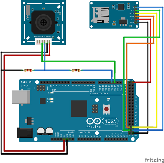
圖1:可以使用Arduino拍攝和存儲照片的設置
因為我們需要大量的RAM來對照片進行解碼,所以我們將使用Arduino Mega。此外,Mega上還有一個額外的有利設計:有四個單獨的硬件串行端口,這樣我們就可以使用Serial1端口與相機進行通信,并使用Serial端口與PC進行通信。
您可能已經注意到了,相機RX線上有一個簡單的電阻分壓器。這是因為VC0706芯片的邏輯電平為3.3V(即使電源電壓為5V),但Arduino Mega的邏輯電平為5V。所以在這里有個善意忠告:當將5V的Arduino和3.3V模塊進行接合時,在RX線上始終至少使用一個分壓器。這比換一個新的模塊要快得多。SD卡讀卡器通過SPI接口直接連接。
既然硬件已經設置好了,那我們就需要開始解決代碼部分了。標準Arduino IDE安裝已經包含了用于SD卡的庫,因此我們從列表中對SD卡進行查看即可。
我們需要控制的另一個設備是VC0706攝像頭。控制過程相對簡單,我們只需要使用串行線發送一些指令,然后通過同一條線接收JPEG照片即可。我們可以編寫一個庫來執行此操作,但是因為這一步我們不需要考慮整體草圖的大小,所以我們將使用Adafruit開發的一個VC0706庫。為了拍攝照片并保存到SD卡上,我們將使用以下代碼,代碼是該庫隨附的經過輕微修改的Snapshot示例。
// Include all the libraries
#include
#include
#include

// Define Slave Select pin
#define SD_CS  53

// Create an instance of Adafruit_VC0706 class
// We will use Serial1 for communication with the camera
Adafruit_VC0706 cam = Adafruit_VC0706(&Serial1);

void setup() {
  // Begin Serial port for communication with PC
  Serial.begin(115200);

  // Start the SD
  if(!SD.begin(SD_CS)) {
    // If the SD can't be started, loop forever
    Serial.println("SD failed or not present!");
    while(1);
  }

  // Start the camera
  if(!cam.begin()) {
    // If the camera can't be started, loop forever
    Serial.println("Camera failed or not present!");
    while(1);
  }

  // Set the image size to 640x480
  cam.setImageSize(VC0706_640x480);
}

void loop() {
  Serial.print("Taking picture in 3 seconds ... ");
  delay(3000);

  // Take a picture
  if(cam.takePicture()) {
    Serial.println("done!");
  } else {
    Serial.println("failed!");
  }

  // Create a name for the new file in the format IMAGExy.JPG
  char filename[13];
  strcpy(filename, "IMAGE00.JPG");
  for(int i = 0; i < 100; i++) {
    filename[5] = '0' + i/10;
    filename[6] = '0' + i%10;
    if(!SD.exists(filename)) {
      break;
    }
  }

  // Create a file with the name we created above and open it
  File imgFile = SD.open(filename, FILE_WRITE);

  // Get the size of the image
  uint16_t jpglen = cam.frameLength();
  Serial.print("Writing ");
  Serial.print(jpglen, DEC);
  Serial.print(" bytes into ");
  Serial.print(filename);
  Serial.print(" ... ");

  // Read all the image data
  while(jpglen > 0) {
    // Load the JPEG-encoded image data from the camera into a buffer
    uint8_t *buff;
    uint8_t bytesToRead = min(32, jpglen);
    buff = cam.readPicture(bytesToRead);

    // Write the image data to the file
    imgFile.write(buff, bytesToRead);
    jpglen -= bytesToRead;
  }

  // Safely close the file
  imgFile.close();

  Serial.println("done!");
  delay(3000);
}
現在,Arduino將每10秒左右拍攝一張照片,直到SD卡上的空間用完為止。但是,由于照片通常約為48kB,并且我目前使用的是2GB的SD卡,因此足夠容納超過43000張的照片。理論上來說我們不需要那么多的照片。但是既然已經拍攝了一些照片,我們現在可以繼續進行下一個有趣環節了:將它們從JPEG壓縮后的難以管理的雜亂數據變成簡單的像素陣列!
解碼和發送照片
在開始解碼前,讓我們快速地看一下圖片數據在JPEG文件中究竟是如何存儲的。如果您對這部分不太感興趣,可以跳過下面三段內容。如果您確切地對圖形和壓縮方面的知識了解一二(不像我這樣),您也可以跳過這一部分。以下內容進行了一定程度的簡化。
對任何類型的圖片數據進行存儲時,有兩種基本方法:無損和有損壓縮。兩者的區別很明顯:當使用無損壓縮(例如PNG)對圖像進行編碼時,處理之后圖像的每個像素都與開始時完全相同。這非常適合于諸如計算機圖形學之類的工作,但是不幸的是,這是以增加文件大小為代價的。另一方面,對于像JPEG這樣的有損壓縮,我們丟失了一些細節,但是生成的文件大小要小得多。
JPEG壓縮方式在理解上可能會有點困難,因為會涉及到一些“離散余弦變換”,不過主要原理實際上是非常簡單的。首先,將圖片從RGB顏色空間轉換為YCbCr。我們都知道RGB顏色空間—它存儲了紅色(R)、綠色(G)和藍色(B)的顏色值。YCbCr有很大的不同—它使用亮度(Y—基本是原始圖像的灰度圖),藍色差分量(Cb—圖片中的“藍色”)和紅色差分量(Cr—圖片中的“紅色”)。
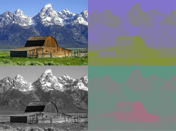
圖2:JPEG照片以及其分離出的色差分量。左上角為原始圖像,左下角為Y分量,右上角為Cb分量,右下角為Cr分量
JPEG減小文件大小的方法實際上與人眼處理顏色的方式密切相關。看一下上圖中的Y、Cb和Cr分量圖。哪一個看起來更像是原始圖片?是的,灰度圖!這是因為人眼對亮度的敏感度要比對其它兩個分量的敏感度高得多。JPEG壓縮就非常聰明地利用了這一點,在保留原始Y分量的同時減少Cb和Cr分量中的信息量。如此一來,生成的圖片就比原始文件小得多,并且由于大多數壓縮信息都位于人眼不太敏感的分量中,因此與未壓縮的圖片相比,您幾乎看不到壓縮圖片的區別。
現在,讓我們開始運行真正實現將JPEG轉換為像素陣列的代碼吧。幸運的是,有一個庫可以做到這一點—Bodmer的JPEGDecoder(可在GitHub上獲得),該庫基于Rich Geldreich(也可在GitHub)上獲取)提供的出色的picojpeg庫。雖然最初編寫JPEGDecoder的目的是在TFT顯示器上顯示圖像,但是將其進行一些細微調整后就可以用于我們的工作了。
該庫的使用非常簡單:我們輸入JPEG文件,然后該庫就會開始產生像素陣列—所謂的最小編碼單位,或簡稱為MCU。MCU是一個16×8的像素塊。庫中的函數將以16位顏色值的形式返回每個像素點的顏色值。高5位是紅色值,中6位是綠色值,低5位是藍色值。現在,我們可以通過任何通信通道來發送這些值。我將使用串行端口,以便之后可以更容易地接收數據。下面的Arduino草圖對一張圖像進行了解碼,然后發送了MCU中每個像素點的16位RGB值,并對圖像文件中的所有MCU重復該操作。
// Include the library
#include

// Define Slave Select pin
#define SD_CS  53

void setup() {
  // Set pin 13 to output, otherwise SPI might hang
  pinMode(13, OUTPUT);

  // Begin Serial port for communication with PC
  Serial.begin(115200);

  // Start the SD
  if(!SD.begin(SD_CS)) {
    // If the SD can't be started, loop forever
    Serial.println("SD failed or not present!");
    while(1);
  }

  // Open the root directory
  File root = SD.open("/");

  // Wait for the PC to signal
  while(!Serial.available());

  // Send all files on the SD card
  while(true) {
    // Open the next file
    File jpgFile = root.openNextFile();

    // We have sent all files
    if(!jpgFile) {
      break;
    }

    // Decode the JPEG file
    JpegDec.decodeSdFile(jpgFile);

    // Create a buffer for the packet
    char dataBuff[240];

    // Fill the buffer with zeros
    initBuff(dataBuff);

    // Create a header packet with info about the image
    String header = "$ITHDR,";
    header += JpegDec.width;
    header += ",";
    header += JpegDec.height;
    header += ",";
    header += JpegDec.MCUSPerRow;
    header += ",";
    header += JpegDec.MCUSPerCol;
    header += ",";
    header += jpgFile.name();
    header += ",";
    header.toCharArray(dataBuff, 240);

    // Send the header packet
    for(int j=0; j<240; j++) {
      Serial.write(dataBuff[j]);
    }

    // Pointer to the current pixel
    uint16_t *pImg;

    // Color of the current pixel
    uint16_t color;

    // Create a data packet with the actual pixel colors
    strcpy(dataBuff, "$ITDAT");
    uint8_t i = 6;

    // Repeat for all MCUs in the image
    while(JpegDec.read()) {
      // Save pointer the current pixel
      pImg = JpegDec.pImage;

      // Get the coordinates of the MCU we are currently processing
      int mcuXCoord = JpegDec.MCUx;
      int mcuYCoord = JpegDec.MCUy;

      // Get the number of pixels in the current MCU
      uint32_t mcuPixels = JpegDec.MCUWidth * JpegDec.MCUHeight;

      // Repeat for all pixels in the current MCU
      while(mcuPixels--) {
        // Read the color of the pixel as 16-bit integer
        color = *pImg++;

        // Split it into two 8-bit integers
        dataBuff[i] = color >> 8;
        dataBuff[i+1] = color;
        i += 2;

        // If the packet is full, send it
        if(i == 240) {
          for(int j=0; j<240; j++) {
            Serial.write(dataBuff[j]);
          }
          i = 6;
        }

        // If we reach the end of the image, send a packet
        if((mcuXCoord == JpegDec.MCUSPerRow - 1) &&
          (mcuYCoord == JpegDec.MCUSPerCol - 1) &&
          (mcuPixels == 1)) {

          // Send the pixel values
          for(int j=0; j
注釋中已經對大多數代碼進行了解釋,但是我還是需要對代碼結構中的“包”進行一些說明。為了使數據傳輸更加有序,所有內容都以包的形式傳輸,最大長度為240字節。包有兩種可能的類型:
1.頭包:此包以字符串“$ITHDR”開頭,并且包含我們將要發送的圖片的基本信息:以像素為單位的高度和寬度,行和列前的MCU數量,最后是原始文件名。對于我們要發送的每個圖像,都會相應發送一個頭包。
2.數據包:該包以“$ITDAT”開頭,并包含所有顏色數據。該數據包中的每兩個字節代表一個16位像素值。
乍一看,包的長度似乎是隨機的。但是為什么恰好是240個字節?為什么不是256個,使我們可以在每個包中發送兩個MCU呢?這是另一個我們日后將會解決的謎團,但是我們可以保證, 數字240不會有任何隨機性。這里有個小提示:如果包中有256個字節的數據,我們要在哪里存儲源地址和目標地址呢?
現在,我們有了一個可以解碼和發送圖片文件的代碼,但是仍然缺少一個核心功能:目前為止,并沒有可以響應這些數據的另一端口。這意味著是時候再次啟用Processing了!
接收圖片
我在Arduino六足機器人第三部分:遠程控制中曾介紹過一些有關Processing的內容,用其編寫了一個應用程序,通過該應用程序我們能夠輕松控制六足機器人。簡單回顧一下:Processing是一種基于Java的語言,主要用于繪圖工作。因此它非常適用于我們現在要做的像素顯示的工作!該程序就是用Processing實現的。
// Import the library
import processing.serial.*;

Serial port;

void setup() {
  // Set the default window size to 200 by 200 pixels
  size(200, 200);

  // Set the background to grey
  background(#888888);

  // Set as high framerate as we can
  frameRate(1000000);

  // Start the COM port communication
  // You will have to replace "COM30" with the Arduino COM port number
  port = new Serial(this, "COM30", 115200);

  // Read 240 bytes at a time
  port.buffer(240);
}

// String to save the trimmed input
String trimmed;

// Buffer to save data incoming from Serial port
byte[] byteBuffer = new byte[240];

// The coordinate variables
int x, y, mcuX, mcuY;

// A variable to measure how long it takes to receive the image
long startTime;

// A variable to save the current time
long currentTime;

// Flag to signal end of transmission
boolean received = false;

// Flag to signal reception of header packet
boolean headerRead = false;

// The color of the current pixel
int inColor, r, g, b;

// Image information variables
int jpegWidth, jpegHeight, jpegMCUSPerRow, jpegMCUSPerCol, mcuWidth, mcuHeight, mcuPixels;

// This function will be called every time any key is pressed
void keyPressed() {
  // Send something to Arduino to signal the start
  port.write('s');
}

// This function will be called every time the Serial port receives 240 bytes
void serialEvent(Serial port) {
  // Read the data into buffer
  port.readBytes(byteBuffer);

  // Make a String out of the buffer
  String inString = new String(byteBuffer);

  // Detect the packet type
  if(inString.indexOf("$ITHDR") == 0) {
    // Header packet

    // Remove all whitespace characters
    trimmed = inString.trim();

    // Split the header by comma
    String[] list = split(trimmed, ',');

    // Check for completeness
    if(list.length != 7) {
      println("Incomplete header, terminated");
      while(true);
    } else {
      // Parse the image information
      jpegWidth = Integer.parseInt(list[1]);
      jpegHeight = Integer.parseInt(list[2]);
      jpegMCUSPerRow = Integer.parseInt(list[3]);
      jpegMCUSPerCol = Integer.parseInt(list[4]);

      // Print the info to console
      println("Filename: " + list[5]);
      println("Parsed JPEG width: " + jpegWidth);
      println("Parsed JPEG height: " + jpegHeight);
      println("Parsed JPEG MCUs/row: " + jpegMCUSPerRow);
      println("Parsed JPEG MCUs/column: " + jpegMCUSPerCol);

      // Start the timer
      startTime = millis();
    }

    // Set the window size according to the received information
    surface.setSize(jpegWidth, jpegHeight);

    // Get the MCU information
    mcuWidth = jpegWidth / jpegMCUSPerRow;
    mcuHeight = jpegHeight / jpegMCUSPerCol;
    mcuPixels = mcuWidth * mcuHeight;

  } else if(inString.indexOf("$ITDAT") == 0) {
    // Data packet

    // Repeat for every two bytes received
    for(int i = 6; i < 240; i += 2) {
      // Combine two 8-bit values into a single 16-bit color
      inColor = ((byteBuffer[i] & 0xFF) << 8) | (byteBuffer[i+1] & 0xFF);

      // Convert 16-bit color into RGB values
      r = ((inColor & 0xF800) >> 11) * 8;
      g = ((inColor & 0x07E0) >> 5) * 4;
      b = ((inColor & 0x001F) >> 0) * 8;

      // Paint the current pixel with that color
      set(x + mcuWidth*mcuX, y + mcuHeight*mcuY, color(r, g, b));

      // Move onto the next pixel
      x++;

      if(x == mcuWidth) {
        // MCU row is complete, move onto the next one
        x = 0;
        y++;
      }

      if(y == mcuHeight) {
        // MCU is complete, move onto the next one
        x = 0;
        y = 0;
        mcuX++;
      }

      if(mcuX == jpegMCUSPerRow) {
        // Line of MCUs is complete, move onto the next one
        x = 0;
        y = 0;
        mcuX = 0;
        mcuY++;
      }

      if(mcuY == jpegMCUSPerCol) {
        // The entire image is complete
        received = true;
      }
    }
  }
}

void draw() {
  // If we received a full image, start the whole process again
  if(received) {

    // Reset coordinates
    x = 0;
    y = 0;
    mcuX = 0;
    mcuY = 0;

    // Reset the flag
    received = false;

    // Measure how long the whole thing took
    long timeTook = millis() - startTime;
    println("Image receiving took: " + timeTook + " ms");
    println();
  }
}
當您在連接Arduino之后運行該程序,然后按下鍵盤上的任意鍵時,您(希望)會看到暗淡、單一的灰色背景逐漸被最初存儲在SD卡上的圖像所取代。由于替換是逐像素進行的,因此整個過程具有一種老式撥號調制解調器的加載圖像風格!
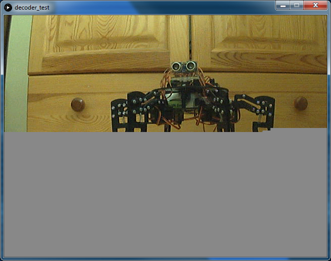
圖3:使用Processing應用程序將照片從Arduino加載到PC
雖然我們以相當高的波特率(準確值為115200)運行串行端口,接收一張圖像也需要大約60秒。我們可以用它來計算實際的傳輸速度。
原始圖像寬640像素,高480像素,總計307200像素。每個像素都由2字節的顏色值來表示,總共要傳輸614400個字節(即600KB)。那么我們的最終速度約為10kB/s。對于我們制定的“協議”來說,這并不算很糟糕,不是嗎?此外,它還向您展示了為什么圖像壓縮如此有用。原始JPEG文件只有48kB左右,而解碼后的位圖則需要600kB。如果我們要傳輸JPEG文件,即使使用非常簡單的“協議”,也可以在5秒之內完成傳輸。當然,萬一傳輸失敗,我們將可能無法追回任何數據—這種情況現在已經不會發生了。
結論
最后,我們證實了本文開頭所說的:在Arduino上處理圖像是可能的,并且在某些情況下可能會更有優勢。現在,我們可以使用串行相機拍攝照片,對其進行解碼,通過串行端口發送,然后在另一端接收了!可以將本文作為您在Arduino上進行圖像處理的入門簡介。
像往常一樣,有很多方面都可以進一步改善。一個需要添加的主要功能可能是使用AES對我們的消息進行加密,這一點很容易實現(即使在Arduino上)。在Arduino上,安全性通常會被忽視,這是很危險的,因此在下一個項目中我們可能會將重點更多地放在安全性上。
感謝您閱讀本文!請繼續關注我們的其他有趣項目!也許有些項目將會使用到我們在本項目中所學到的所有內容!
審核編輯黃宇
-
解碼
+關注
關注
0文章
189瀏覽量
28710 -
JPEG
+關注
關注
0文章
66瀏覽量
30803 -
Arduino
+關注
關注
190文章
6526瀏覽量
196900
發布評論請先 登錄
【NanoPi NEO2試用體驗】libjpeg庫的使用之jpeg解碼
JPEG圖像硬件解碼低功耗技術方案
jpeg格式圖片疊加bmp或png格式水印操作資料下載
如何使用FPGA實現JPEG解碼算法的研究與實現論文免費下載


 工商網監
工商網監
評論