") FPGA與MCU的程序思路
FPGA與MCU的程序思路

FPGA以9600的波特率向單片機發(fā)送32位數(shù)據(jù),然后單片機對數(shù)據(jù)進行解析,顯示在顯示屏上面
波特率的產(chǎn)生 :9600bps是指每秒鐘發(fā)送9600個bit,即1bit的時間為1/9600,fpga板子自帶50M晶振,那么一bit的時間時1/9600/1/50M
在沒有檢驗位的情況下,每一幀數(shù)據(jù)是10位 第一位起始位 0 2-9位 數(shù)據(jù)(低位在前,高位在后),第十位 終止位 1
FPGA程序思路 :首先由fpga計數(shù),每隔一段時間產(chǎn)生一個bps_clk,也就是波特率的驅(qū)動時鐘,發(fā)送狀態(tài)機共分為7個狀態(tài)
IDLE :發(fā)送起始標(biāo)志為 TX_1 :發(fā)送32數(shù)據(jù)的高八位,其中低位在前,高位在后 ...... STOP :終止標(biāo)志位 STOP_1 : 是專門用來延時的,剛開始沒有延時狀態(tài)
的情況下,F(xiàn)PGA向單片機發(fā)送數(shù)據(jù)過快,非常占用單片機的中斷資源,所以加了一個延時模塊 stop ,作用是:每發(fā)完一次數(shù)據(jù)等待100ms然后再發(fā)第二次數(shù)據(jù),這樣的
單片機就有時間干別的事情了。
MCU程序思路 :首先在中斷函數(shù)里面將FPGA發(fā)送過來的數(shù)據(jù)存到一個數(shù)組里面來處理,detect-uart()函數(shù)是用來分析數(shù)組的,首先檢測數(shù)組里面的起始標(biāo)志 ‘t’,如果沒有檢測到
終止標(biāo)志位‘x’的話,對中間數(shù)據(jù)進行移位處理,還原以前的32位寬的數(shù)據(jù),由于在數(shù)據(jù)傳送時有誤碼的情況,所以在display中加了三級緩存,來減少出錯的可能性。
module    uart_tx(
        //global clock
        input            clk,
        input            rst_n,
        //uart    interface
        output    reg        uart_tx,
        //user    interface
        input    [31:0]    pinlv,
        input            pinlv_value
);

parameter    BPS_9600 = 5208;
//parameter    BPS_9600 = 10;
//count for bps_clk
reg        [14:0]        cnt_bps_clk;
always @(posedge clk or negedge rst_n)
begin
    if(!rst_n)
        cnt_bps_clk <= 1'b0;
    else if(pinlv_value == 0)
        cnt_bps_clk <= 1'b0;
    else if(cnt_bps_clk == BPS_9600 - 1)
        cnt_bps_clk <= 1'b0;
    else
        cnt_bps_clk <= cnt_bps_clk + 1;
end

reg        [31:0]        cnt_bps_stop;
wire                stop_done;
always @(posedge clk or negedge rst_n)
begin
    if(!rst_n)
        cnt_bps_stop <= 0;
    else if(state == STOP)
        cnt_bps_stop <= 0;
    else if(cnt_bps_stop > 50_000_00)
        cnt_bps_stop <= 0;
    else
        cnt_bps_stop <= cnt_bps_stop + 1;

end
assign    stop_done = (cnt_bps_stop == 49_000_00)? 1 : 0;
//clk for bps
reg                    bps_clk;
always @(posedge clk or negedge rst_n)
begin
    if(!rst_n)
        bps_clk <= 1'b0;
    else if(cnt_bps_clk == 1)
        bps_clk <= 1'b1;
    else
        bps_clk <= 1'b0;
end
//cnt for bps
reg        [14:0]        bps_cnt;
always @(posedge clk or negedge rst_n)
begin
    if(!rst_n)
        bps_cnt <= 1'b0;
    else if(bps_cnt == 10)
        bps_cnt <= 0;
    else if(bps_clk)
        bps_cnt <= bps_cnt + 1'b1;
    else
        bps_cnt <= bps_cnt;
end

//tx state
localparam    IDLE        =    4'd0;
localparam    TX_1        =    4'd1;
localparam    TX_2        =    4'd2;
localparam    TX_3        =    4'd3;
localparam    TX_4        =    4'd4;
localparam    STOP        =    4'd5;
localparam    STOP_1        =    4'd6;
//cnt state
reg        [3:0]        state;
always @(posedge clk or negedge rst_n)
begin
    if(!rst_n)
        state <= IDLE;
    else if(state == STOP_1 && stop_done)
        state <= IDLE;
    else if(bps_cnt == 10 && (state != STOP_1))
        state <= state + 1;
end


// state
always @(posedge clk )
begin
    if(bps_clk)
    begin
        case(state)
        IDLE :   // 't'  di -- gao
        begin
            case(bps_cnt)
            4'd0     : uart_tx <= 0; //begin

            4'd1     : uart_tx <= 0;//data
            4'd2     : uart_tx <= 0;
            4'd3     : uart_tx <= 1;
            4'd4     : uart_tx <= 0;
            4'd5     : uart_tx <= 1;
            4'd6    : uart_tx <= 1;
            4'd7     : uart_tx <= 1;
            4'd8     : uart_tx <= 0;

            4'd9     : uart_tx <= 1; //stop
            default : uart_tx <= 1;
            endcase
        end

        TX_1 : //tx_1byte
        begin
            case(bps_cnt)
            4'd0 : uart_tx <= 0; //begin

            4'd1     : uart_tx <= pinlv[24];//data
            4'd2     : uart_tx <= pinlv[25];
            4'd3     : uart_tx <= pinlv[26];
            4'd4     : uart_tx <= pinlv[27];
            4'd5     : uart_tx <= pinlv[28];
            4'd6    : uart_tx <= pinlv[29];
            4'd7     : uart_tx <= pinlv[30];
            4'd8     : uart_tx <= pinlv[31];

            4'd9     : uart_tx <= 1; //stop
            default : uart_tx <= 1;
            endcase
        end

        TX_2 : //tx_1byte
        begin
            case(bps_cnt)
            4'd0 : uart_tx <= 0; //begin

            4'd1     : uart_tx <= pinlv[16];//data
            4'd2     : uart_tx <= pinlv[17];
            4'd3     : uart_tx <= pinlv[18];
            4'd4     : uart_tx <= pinlv[19];
            4'd5     : uart_tx <= pinlv[20];
            4'd6    : uart_tx <= pinlv[21];
            4'd7     : uart_tx <= pinlv[22];
            4'd8     : uart_tx <= pinlv[23];

            4'd9     : uart_tx <= 1; //stop
            default : uart_tx <= 1;
            endcase
        end


        TX_3 : //tx_1byte
        begin
            case(bps_cnt)
            4'd0 : uart_tx <= 0; //begin

            4'd1     : uart_tx <= pinlv[8];//data
            4'd2     : uart_tx <= pinlv[9];
            4'd3     : uart_tx <= pinlv[10];
            4'd4     : uart_tx <= pinlv[11];
            4'd5     : uart_tx <= pinlv[12];
            4'd6    : uart_tx <= pinlv[13];
            4'd7     : uart_tx <= pinlv[14];
            4'd8     : uart_tx <= pinlv[15];

            4'd9     : uart_tx <= 1; //stop
            default : uart_tx <= 1;
            endcase
        end

        TX_4 : //tx_1byte
        begin
            case(bps_cnt)
            4'd0 : uart_tx <= 0; //begin

            4'd1     : uart_tx <= pinlv[0];//data
            4'd2     : uart_tx <= pinlv[1];
            4'd3     : uart_tx <= pinlv[2];
            4'd4     : uart_tx <= pinlv[3];
            4'd5     : uart_tx <= pinlv[4];
            4'd6    : uart_tx <= pinlv[5];
            4'd7     : uart_tx <= pinlv[6];
            4'd8     : uart_tx <= pinlv[7];

            4'd9     : uart_tx <= 1; //stop
            default : uart_tx <= 1;
            endcase
        end

        STOP :   // 'x'  di -- gao
        begin
            case(bps_cnt)
            4'd0 : uart_tx <= 0; //begin

            4'd1     : uart_tx <= 0;//data
            4'd2     : uart_tx <= 0;
            4'd3     : uart_tx <= 0;
            4'd4     : uart_tx <= 1;
            4'd5     : uart_tx <= 1;
            4'd6    : uart_tx <= 1;
            4'd7     : uart_tx <= 1;
            4'd8     : uart_tx <= 0;

            4'd9     : uart_tx <= 1; //stop
            default : uart_tx <= 1;
            endcase
        end

        STOP_1 :
        begin
            uart_tx <= 1;
        end

        default :
            uart_tx <= 1;
        endcase
    end
    else
        uart_tx <= uart_tx;

end


endmodule
/*************** 用戶定義參數(shù) *****************************/ #define MAIN_Fosc 11059200L //define main clock #define Baudrate1 9600 //define the baudrate, 如果使用BRT做波特率發(fā)生器,則波特率跟串口2一樣 //12T mode: 600~115200 for 22.1184MHZ, 300~57600 for 11.0592MHZ #define Baudrate2 19200 //define the baudrate2, //12T mode: 600~115200 for 22.1184MHZ, 300~57600 for 11.0592MHZ #define BUF_LENTH 20 //定義串口接收緩沖長度 /**********************************************************/ #includesfr AUXR1 = 0xA2; sfr AUXR = 0x8E; sfr S2CON = 0x9A; //12C5A60S2雙串口系列 sfr S2BUF = 0x9B; //12C5A60S2雙串口系列 sfr IE2 = 0xAF; //STC12C5A60S2系列 sfr BRT = 0x9C; unsigned char uart1_wr; //寫指針 unsigned char uart1_rd; //讀指針 unsigned char xdata RX1_Buffer[BUF_LENTH]; bit B_TI; unsigned char uart2_wr; //寫指針 unsigned char uart2_rd; //讀指針 unsigned char xdata RX2_Buffer[BUF_LENTH]; bit B_TI2; long temp1 = 0; long temp2 = 0; long temp_buf1 = 0; long temp_buf2 = 0; long temp_buf3 = 0; long temp_buf = 0; long ce = 9999; /****************** 編譯器自動生成,用戶請勿修改 ************************************/ #define T1_TimerReload (256 - MAIN_Fosc / 192 / Baudrate1) //Calculate the timer1 reload value at 12T mode #define BRT_Reload (256 - MAIN_Fosc / 12 / 16 / Baudrate2) //Calculate BRT reload value #define TimeOut1 (28800 / (unsigned long)Baudrate1 + 2) #define TimeOut2 (28800 / (unsigned long)Baudrate2 + 2) #define TI2 (S2CON & 0x02) != 0 #define RI2 (S2CON & 0x01) != 0 #define CLR_TI2() S2CON &= ~0x02 #define CLR_RI2() S2CON &= ~0x01 /**********************************************************/ /******************** 本地函數(shù)聲明 ***************/ void uart1_init(void); void UART1_TxByte(unsigned char dat); void PrintString1(unsigned char code *puts); void delay(char x) { char i = 0; char t= 0; for(i = 0;i<110;i++) { for(t = 0;t < x;t++); } } void detect_uart() { char i = 0; char flag = 0; temp1 = 0; for(i = 0;i <= uart1_wr ; i++) { // UART1_TxByte(RX1_Buffer[i]); if(flag) { if(RX1_Buffer[i] != 'x' ) { temp1 = temp1 << 8 ; temp1 = temp1 + RX1_Buffer[i]; // UART1_TxByte(RX1_Buffer[i]); } else temp2 = temp1; } if(RX1_Buffer[i] == 't') { flag = 1; } } } //void ceshi() //{ // ce = 0; // ce = ce << 8 ; // ce = ce + 0xff; // ce = ce << 8 ; // ce = ce + 0x0c; // ce = ce << 8 ; // ce = ce + 0xcc; // ce = ce << 8 ; // ce = ce + 0xcc; //// ce = 9999; //} void display() { char flag = 0; temp_buf3 = temp_buf2; temp_buf2 = temp_buf1; temp_buf1 = temp2; if(temp_buf3 == temp2) { temp_buf = temp2; } else { temp_buf = temp_buf; } UART1_TxByte('S');UART1_TxByte(' ');UART1_TxByte(' ');UART1_TxByte(' ');UART1_TxByte(' '); if(temp_buf/100000000 == 0) //bai M { UART1_TxByte(' '); } else { UART1_TxByte(temp_buf/100000000 + 0x30); flag = 1; } if(temp_buf/10000000%10 == 0 ) //shi M { if(!flag) { UART1_TxByte(' '); } else { UART1_TxByte(0x30); } } else { UART1_TxByte(temp_buf/10000000%10 + 0x30); flag = 1; } if(temp_buf/1000000%10 == 0 ) //M { if(!flag) { UART1_TxByte(' '); } else { UART1_TxByte(0x30); } } else { UART1_TxByte(temp_buf/1000000%10 + 0x30); flag = 1; } if(temp_buf/100000%10 == 0 ) //bai K { if(!flag) { UART1_TxByte(' '); } else { UART1_TxByte(0x30); } } else { UART1_TxByte(temp_buf/100000%10 + 0x30); flag = 1; } if(temp_buf/10000%10 == 0 ) //shi k { if(!flag) { UART1_TxByte(' '); } else { UART1_TxByte(0x30); } } else { UART1_TxByte(temp_buf/10000%10 + 0x30); flag = 1; } if(temp_buf/1000%10 == 0 ) // K { if(!flag) { UART1_TxByte(' '); } else { UART1_TxByte(0x30); } } else { UART1_TxByte(temp_buf/1000%10 + 0x30); flag = 1; } if(temp_buf/100%10 == 0 ) //bai { if(!flag) { UART1_TxByte(' '); } else { UART1_TxByte(0x30); } } else { UART1_TxByte(temp_buf/100%10 + 0x30); flag = 1; } if(temp_buf/10%10 == 0 ) //shi { if(!flag) { UART1_TxByte(' '); } else { UART1_TxByte(0x30); } } else { UART1_TxByte(temp_buf/10%10 + 0x30); flag = 1; } if(temp_buf%10 == 0 ) //ge { if(!flag) { UART1_TxByte(' '); } else { UART1_TxByte(0x30); } } else { UART1_TxByte(temp_buf%10 + 0x30); flag = 1; } } void main(void) { char i = 0; uart1_rd = 0; uart1_wr = 0; uart2_rd = 0; uart2_wr = 0; // AUXR |= 0x01; //串口1使用獨立波特率發(fā)生器, 波特率跟串口2一樣 AUXR1 |= (1<<4); //將UART2從P1口切換到 RXD2--P1.2切換到P4.2 TXD2---P1.3切換到P4.3 uart1_init(); PrintString1("串口1測試程序"); while(1) { display(); detect_uart(); } } void UART1_TxByte(unsigned char dat) { B_TI = 0; SBUF = dat; while(!B_TI); B_TI = 0; delay(10); } void PrintString1(unsigned char code *puts) //發(fā)送一串字符串 { for (; *puts != 0; puts++) UART1_TxByte(*puts); //遇到停止符0結(jié)束 } void uart1_init(void) { PCON |= 0x80; //UART0 Double Rate Enable SCON = 0x50; //UART0 set as 10bit , UART0 RX enable TMOD &= ~(1<<6); //Timer1 Set as Timer, 12T TMOD = (TMOD & ~0x30) | 0x20; //Timer1 set as 8 bits auto relaod TH1 = T1_TimerReload; //Load the timer TR1 = 1; ES = 1; EA = 1; } /**********************************************/ void UART0_RCV (void) interrupt 4 { if(RI) { RI = 0; RX1_Buffer[uart1_wr] = SBUF; if(++uart1_wr >= BUF_LENTH) uart1_wr = 0; } if(TI) { TI = 0; B_TI = 1; } }
原文標(biāo)題:MCU與FPGA串口通信
文章出處:【微信公眾號:FPGA之家】歡迎添加關(guān)注!文章轉(zhuǎn)載請注明出處。
-
FPGA
+關(guān)注
關(guān)注
1660文章
22412瀏覽量
636388 -
單片機
+關(guān)注
關(guān)注
6076文章
45495瀏覽量
670442 -
mcu
+關(guān)注
關(guān)注
147文章
18925瀏覽量
398288
原文標(biāo)題:MCU與FPGA串口通信
文章出處:【微信號:zhuyandz,微信公眾號:FPGA之家】歡迎添加關(guān)注!文章轉(zhuǎn)載請注明出處。
發(fā)布評論請先 登錄
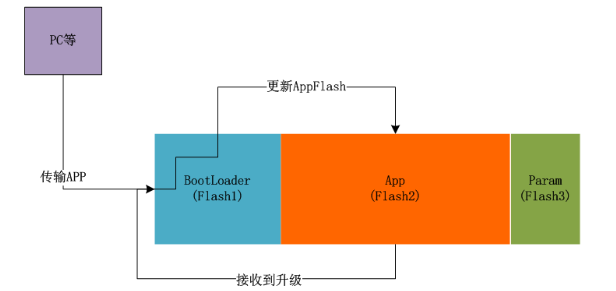
MCU軟件升級設(shè)計思路分析
xilinx-A7 fpga 使用QSPI模式啟動,項目需要用MCU做FPGA程序升級,請問MCU怎么操作SPIFLASH?
基于MCU和FPGA的數(shù)字式相位測量儀的設(shè)計
聚焦電子創(chuàng)新設(shè)計,分享MCU技術(shù)新思路
FPGA設(shè)計的思路和方法初探詳細(xì)資料免費下載
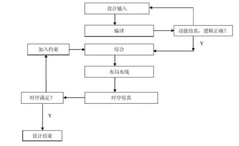
FPGA教程之FPGA系統(tǒng)設(shè)計的主要思路和方法初探資料說明
AGM MCU+FPGA

FPGA MCU FSMC通信接口——NAND Flash模式
遠(yuǎn)程升級單片機程序設(shè)計思路


 工商網(wǎng)監(jiān)
評論