 0.7~24V連續可調限流電源,0.7 ~ 24V adjustable current-limiting power supply

0.7~24V連續可調限流電源,0.7 ~ 24V adjustable current-limiting power supply
關鍵字:0.7~24V連續可調限流電源
0.7~24V連續可調限流電源
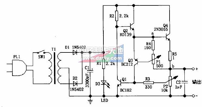
圖中的電路可以實現輸出電壓0.7~24V連續可調,并且可以實現50mA~2A可調的最大輸出電流限制。
P1用來設置輸出電流最大限值,調整它可以在相應的輸出電壓時,給出50mA~2A的電流限制。P1設置輸出電流最大限值的原理如下:從圖中可以看出,輸出電流主要來自Q4的發射極,這樣,當輸出電流增大,電路中a、b點間的電壓也跟著增大,這時,a點(即Q3的e極)和Q3的b極間的電壓也增大,而Q3的e、b極間電壓不可能超過0.7V,當Q3的e、b極間電壓增大時,Q3的e極會分流走流往Q4的b極的電流,這樣,就限制了a、b點間電壓的增大,從而實現最大輸出電流限制的目的。
P2用做輸出電壓調節。當輸出電壓增大,Q1的e、b極間電壓也增大,這導致Q1分流走流往Q2的b極的電流,Q2導通電流下降后,不難看出Q4的導通電流也下降,從而使輸出電壓下降。當輸出電壓減小時,原理類似。
P2建議用對數型的電位器,這樣輸出電壓的可調性和線性會更好些。
電源變壓器的輸出電壓和容量應根據你所需要的輸出電壓和電流來選區。最佳的方案是:變壓器次級電壓為36、40、48V或帶中間抽頭的50、75、80V,容量為100VA。
電容C1可以從2200~6800uF/35~50V之間選擇。
電路中,BC182為50V/100mA/NPN三極管,BD139為80V/1.5A/NPN三極管,BC212為50v/100mA/PNP三極管,2N3055為60V/15A/NPN三極管。Q4必須使用散熱器,另外它可以使用TIP3055代替。
google translate:
0.7 ~ 24V continuously adjustable current limiting power supply
The circuit diagram can be achieved output voltage 0.7 ~ 24V continuously adjustable, and can be adjusted to achieve 50mA ~ 2A maximum output current limit.
P1 is used to set the maximum output current limit, you can adjust the output voltage in the corresponding given 50mA ~ 2A current limit. P1 to set the maximum output current limit of the principle is as follows: As can be seen from the diagram, mainly from the Q4 output current emitter, so that when the output current increases, the circuit in a, b points, also followed the voltage between the increase Then, a point (that is Q3 of e pole) and Q3 of the b pole voltage between the increase and Q3 of the e, b can not exceed the voltage between 0.7V, when the Q3 of e, b the voltage between electrodes increased time, Q3 e-flow to the most would be diverted away most of the current Q4 of b, so that the limits a, b point between voltage increases, the maximum output current limit in order to achieve the purpose.
P2 used as the output voltage regulation. When the output voltage increases, Q1 of the e, b the voltage between electrodes is also increased, leading to the Q2 Q1 flow diversion away the b-polar current, Q2 conduction current decreases, not difficult to see Q4 current will also decrease so that the output voltage drops. When output voltage decreases, the principle of similar.
P2 suggested logarithmic potentiometers, so the output voltage is adjustable and linear will be better.
Power transformer output voltage and capacity you need should be based on the output voltage and current to constituency. The best option is: Transformer secondary voltage 36,40,48 V or with intermediate tap 50,75,80 V, capacity of 100VA.
Capacitor C1 can be 2200 ~ 6800uF/35 ~ 50V to choose between.
Circuit, BC182 transistor for the 50V/100mA/NPN, BD139 to 80V/1.5A/NPN transistor, BC212 to 50v/100mA/PNP transistor, 2N3055 transistor to 60V/15A/NPN. Q4 must use the radiator, while it can use TIP3055 replace.
聲明:本文內容及配圖由入駐作者撰寫或者入駐合作網站授權轉載。文章觀點僅代表作者本人,不代表電子發燒友網立場。文章及其配圖僅供工程師學習之用,如有內容侵權或者其他違規問題,請聯系本站處理。
舉報投訴
發布評論請先 登錄
相關推薦
熱點推薦
芯片無內置?前端更可靠!為24V輸入電源模塊構筑過壓防火墻
導讀P2412FKS-1WX是一款具備獨立前端過壓保護的24V轉12V隔離電源模塊。其硬件級保護電路響應迅速、閾值可定制,能可靠防護電壓浪涌,適用于工業、車載、通信等嚴苛供電環境,體現“安全即核心

RAA211230:高性能24V 3A集成開關穩壓器的設計與應用
RAA211230:高性能24V 3A集成開關穩壓器的設計與應用 作為電子工程師,在電源管理領域,我們總是在尋找性能卓越、功能豐富且易于使用的穩壓器。今天,我將為大家詳細介紹Renesas
從安全電壓到致命隱患:24V工業電源EMC防護實戰指南
超鏈接引導行業圖譜EMC保護方案大全國外品牌替代表EMC行業標準雷卯實驗室免費測試雷卯產品規格書講解一.24V系統為何成工業設備"隱形殺手"全球工業電源故障中,24V系統占比高

?SL1590Q 24V/8A高效同步降壓轉換器:高性能電源方案
在消費電子、智能顯示設備對高效率電源需求日益增長的背景下,深圳市森利威爾電子推出的?SL1590Q 24V/8A同步降壓型轉換器?,憑借?4.5V-24V寬工作電壓范圍?和?先進ACOT控制架構
發表于 11-04 16:43
24V通信電源選哪家?廣州郵科靠譜嗎?一文說清真實體驗!
在通信基站、監控系統、工業控制、甚至安防設備里,你可能看不見它,但它每天都在默默“供電”——它就是24V通信電源。別看只是個“電源”,一旦出問題,整個系統可能直接“癱瘓”。那市面上那么多品牌,
24V、1000MHz 高輸出功率倍頻器線路放大器 MMIC skyworksinc
電子發燒友網為你提供()24V、1000MHz 高輸出功率倍頻器線路放大器 MMIC相關產品參數、數據手冊,更有24V、1000MHz 高輸出功率倍頻器線路放大器 MMIC的引腳圖、接線圖、封裝手冊
發表于 08-29 18:33

4.2V/7.4V/12.6V升壓24V【電源設計】解決方案——FP6295關鍵參數和測試全解析
,而多節鋰電池串聯應用同樣需要高效、穩定的升壓方案。FP6295作為一款專為升壓應用設計的電流模式DC-DC轉換器,憑借其寬輸入電壓范圍(2.6V-24V)、高達24V的可調輸出以及90%以上的轉換效率,
ADP5071接負載后負壓24V,變成0到-24V的鋸齒波,為什么?
ADP5071設計±24V,測試無負載時±24v可以測試出來,但是接負載后負壓24V,變成0到-24V的鋸齒波,目前做過如下調整
1、開關頻率1.2MHz,電感15UH,Comp2的
發表于 06-20 08:17
廣州郵科220V變24V開關電源:技術引領,穩定供電新選擇
在當今快速發展的電子科技領域,電源轉換技術作為支撐各種設備穩定運行的核心技術之一,正不斷迎來新的突破與創新。廣州郵科,作為業界知名的電力設備供應商,其推出的220V變24V開關電源,憑
多節電池系統升壓設計:基于FP6295的24V輸出方案實測數據分享
支持的寬輸入電壓范圍為 2.6V - 24V,啟動電壓僅需 2.6V,輸出電壓可調最高至 24V,這種靈活性使其能夠適配多種
國產升壓芯片如何單節鋰電3.7V升壓24V或4.2V升壓24V
發熱問題,提升系統可靠性。
3. ?輸出靈活,支持24V及以上高壓?
芯片內置?可調反饋電阻?,輸出電壓可自由設定在?5V-32V?區間,輕松滿足24V/28
發表于 04-23 11:11
SL4013芯片三節鋰電11V-12.6V升24V和 USB 5V升壓24V
SL4013 芯片在三節鋰電池(11V-12.6V)和 USB 5V 升壓至 24V 的應用中展現出以下技術特性和實現方案:
一、三節鋰電池升壓 24V 方案
輸入電壓適配?
支持
發表于 04-08 10:33
24V轉12V~3V降壓芯片和線性LDO選型
大貨車的電箱電池電量是24V,小轎車的電箱電池電量是12V,在車充中,就需要用到24V轉5V給手機充電的芯片。還有是24V的適配器,穩壓降壓
升壓 SL4013單節鋰電池3.7V升壓至24V? 7.4V升壓至24V?
一、單節鋰電池(3.7V-4.2V)升壓至24V?
單節鋰電池的標稱電壓為3.7V(滿電4.2V),直接升壓至24V需要較大的電壓增益。S
發表于 03-29 09:19
請問各位大神 將220v交流電降壓變為24v后整流濾波穩壓怎么才可以得到0-30v的可調電壓呢?
請問各位大神 將220v交流電降壓變為24v后整流濾波穩壓怎么才可以得到0-30v的可調電壓呢 并且要用stm32數控 能否幫我提供一個思路
發表于 03-10 11:52


 工商網監
工商網監
評論