") 怎樣用繼電器板和ESP8266實(shí)現(xiàn)家居自動(dòng)化
怎樣用繼電器板和ESP8266實(shí)現(xiàn)家居自動(dòng)化

硬件
此版本的主要組件是一個(gè)簡單的繼電器板,可用于切換高達(dá)250V AC的電壓和10安培的最大電流:
用于高壓項(xiàng)目的簡單繼電器板。
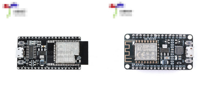
它將由基于ESP8266的IoT開發(fā)板控制,該開發(fā)板與Arduino IDE完全兼容。或者,您也可以使用標(biāo)準(zhǔn)的Arduino和ESP8266(或類似的)分線板。
ESP8266。
你只有需要在這些設(shè)備之間建立兩個(gè)連接。其中一個(gè)是接地,另一個(gè)是用于切換繼電器的控制線,我選擇連接到開發(fā)板的D2(數(shù)字引腳2)。
繼電器和MCU需要連接到一個(gè)五伏電源,在我的情況下,用一個(gè)簡單的直流插孔完成。
除此之外,你還需要一個(gè)標(biāo)準(zhǔn)的電源插座,一個(gè)IEC插頭,最好是一個(gè)帶有接地的插頭。引腳和用于打開和關(guān)閉MCU的開關(guān)。此外,還需要一個(gè)外殼。我選擇使用標(biāo)準(zhǔn)灰色項(xiàng)目框:
使用標(biāo)準(zhǔn)灰色項(xiàng)目框來容納構(gòu)建。
構(gòu)建
構(gòu)建此設(shè)備的過程非常簡單。首先在機(jī)箱中制作必要的剪切:
在項(xiàng)目框中進(jìn)行必要的剪切。
創(chuàng)建它們后,你可以安裝組件。大多數(shù)組件都會(huì)卡入到位。我仍然決定添加熱膠來密封外殼,這樣灰塵就不會(huì)輕易進(jìn)入:
使用膠水確保沒有任何動(dòng)作,并使盒子不易受灰塵影響。
完成后,是時(shí)候連接這些組件和其他電子設(shè)備了。我在三根電源線的一側(cè)添加了電纜鞋并將它們連接到IEC連接器:
在三根電源線的一側(cè)添加電纜鞋并連接到IEC連接器。
可以交換相位和中性線(歐洲的棕色和藍(lán)色,美國的黑色/紅色和白色)。然而,地球連接必須在中間。我將相連接到電源插座并將中性線連接到繼電器的COM2端子,然后將繼電器的NO2(常開)端子連接到插座:
將相位連接到電源插座并將中性線連接到COM2端子在將繼電器的NO2(常開)端子連接到插座之前的繼電器。
然后我將必要的電纜添加到DC插頭。它們用于向微控制器和繼電器提供電壓。最后要做的是連接繼電器和MCU,如上所述。然后我將熱縮管添加到關(guān)鍵部分以防止短路并測試組件:
將必要的電纜添加到DC插頭。
一旦一切都適合,收起電纜并關(guān)閉外殼。
軟件
在MCU上運(yùn)行的軟件將您連接到無線網(wǎng)絡(luò),并像在Web服務(wù)器上一樣接受端口80上的客戶端請求。然后,您可以通過任何Web瀏覽器訪問該設(shè)備:
通過任何網(wǎng)絡(luò)瀏覽器訪問設(shè)備。
我不會(huì)討論詳細(xì)的代碼,以保持文章簡短。但是,我詳細(xì)記錄了源代碼,因此應(yīng)該很容易理解。它可以在文章末尾找到。
結(jié)論
正如你所看到的,它是構(gòu)建這樣的設(shè)備并不是非常困難。大部分工作都是由軟件完成的。雖然這是最基本的方法,但您可以添加傳感器,計(jì)時(shí)器和其他設(shè)備來自動(dòng)控制連接的設(shè)備。此外,如果您計(jì)劃在無人看管的情況下使用此設(shè)備,我建議添加保險(xiǎn)絲。
完整的項(xiàng)目代碼
#include
#define RELAY_PIN D2
const char* ssid = “YOUR_WIFI_NETWORK”;
const char* pass = “YOUR_NETWORKS_PASSWORD”;
WiFiServer server(80);
void setup()
{
Serial.begin(9600);
// You could add an EEPROM to store the last state if the device gets powered off.
// See: https://maker.pro/arduino/tutorial/how-to-permanently-store-data-on-your-arduino
//
// It‘s also possible to store the website and stylesheets/additional scripts on an SD
// card and display the files to a client when they connect.
// See: https://maker.pro/arduino/tutorial/how-to-use-an-sd-card-with-your-arduino
//
// However, this simple example will always start with the relay turned on and a very
// basic HTML page with two buttons.
pinMode(RELAY_PIN, OUTPUT);
digitalWrite(RELAY_PIN, HIGH);
// Connect to your local network
WiFi.begin(ssid, pass);
while (WiFi.status() != WL_CONNECTED)
delay(250);
Serial.print(“Connected to network: ”);
Serial.println(ssid);
// Start the server
// A client will connect to this server to change the state of the relay
server.begin();
Serial.print(“Server started with address: ”);
Serial.print(“http://”);
Serial.print(WiFi.localIP());
Serial.println(“/”);
}
void loop()
{
// Check for incoming connections
WiFiClient client = server.available();
if (!client)
return;
// Wait for the client to send data
while(!client.available())
delay(5);
// Read the first line of the HTTP request
// which will contain something like
// METHOD /requested_url HTTP_VERSION
// for example:
// PUT /dev2?relay=1&state=on HTTP/1.1
// However, for the sake of simplicity this device will
// respond to GET requests so that they can be sent with
// any web browser. Requests to this device will look
// similar to this:
// GET /state=on HTTP/1.1
String request = client.readStringUntil(’ ‘);
client.flush();
int state = 0, error = 0;
// Check, whether the request contains “/state=”
if (request.indexOf(“state=”) != -1)
{
// HIGH and LOW are swapped in this program because my
// relay is turned on when its input pin is pulled LOW.
if(request.indexOf(“state=on”) != -1)
{
digitalWrite(RELAY_PIN, HIGH);
state = LOW;
}
else if (request.indexOf(“state=off”) != -1)
{
digitalWrite(RELAY_PIN, LOW);
state = HIGH;
}
else
{
error = 1;
Serial.print(“Unknown request: ”);
Serial.println(request);
}
}
// Return the response
// If no error occurred, send an HTML page with two buttons
// so that the device can be managed.
// Otherwise, send an error message
if(error == 0)
{
// Return a response header
client.println(“HTTP/1.1 200 OK”);
client.println(“Content-Type: text/html”);
// The HTTP response body is separated from the header by an empty line
// (actually a line containing , but this will work)
client.println(“”);
// Return the response body (an html page)
client.println(“”);
client.println(“”);
client.println(“”);
client.println(“”);
client.println(“”);
client.print(“The relay is turned ”);
client.print(state==HIGH?“on”:“off”);
client.println(“
”);
client.println(“Change state:”);
client.println(“Device on”);
client.println(“Device off”);
client.println(“”);
client.println(“”);
}
else
{
// Return a response header
client.println(“HTTP/1.1 400 Bad Request”);
client.println(“Content-Type: text/html”);
client.println(“”);
client.println(“”);
client.println(“Unknown request parameter supplied!
”);
client.println(“Back to main page”);
client.println(“”);
}
}
-
繼電器
+關(guān)注
關(guān)注
133文章
5566瀏覽量
154844 -
ESP8266
+關(guān)注
關(guān)注
51文章
970瀏覽量
49526
發(fā)布評(píng)論請先 登錄
【ESP8266系列】WT8266-S3模組規(guī)格書

【ESP8266系列】WT8266-S5模組規(guī)格書
【ESP8266系列】WT8266-S6模組規(guī)格書
【ESP8266系列】WT8266-S1模組產(chǎn)品介紹
【ESP8266系列】WT8266-S6模組產(chǎn)品介紹
【瑞薩RA6E2地奇星開發(fā)板試用】基于RA6E2+ESP8266在STA模式下數(shù)據(jù)透傳到Python服務(wù)器整體系統(tǒng)演示總結(jié)
【瑞薩RA6E2地奇星開發(fā)板試用】使用`RA6E2`驅(qū)動(dòng) `ESP8266 WiFi模塊`,調(diào)試AT指令。
【瑞薩RA6E2地奇星開發(fā)板試用】使用RA6E2驅(qū)動(dòng) esp8266 WiFi模塊進(jìn)行串口通信【已修復(fù)】
基于芯源CW32 MCU智能家居照明控制系統(tǒng)設(shè)計(jì)與實(shí)現(xiàn)
晶科鑫 | 國產(chǎn)26MHz晶振匹配Espressif(樂鑫) ESP8285/ESP8266芯片案例

ESP8266和ESP32開發(fā)板常見的2種下載方式
ESP8266和ESP32開發(fā)板常見的2種下載方式
STM32+esp8266連接機(jī)智云,上傳溫濕度數(shù)據(jù)并控制繼電器開關(guān)(平臺(tái)配置、代碼生成、代碼移植)

ESP8266燒錄與機(jī)智云一鍵配網(wǎng)教程


 工商網(wǎng)監(jiān)
評(píng)論